1年前に書いたTimer Camera Fで定点カメラを作ってLINEに通知が2022/8/11時点でうまく動かないことがわかりました。修正箇所を記載します。
「Arduino」タグの記事が4件件あります
全てのタグを見るTimer Camera Fで定点カメラを作ってLINEに通知
過去にQiitaに投稿した内容のアーカイブです。
2022/08/30更新 久しぶりに試すとうまく動きませんでした。修正箇所をこちらにまとめています。
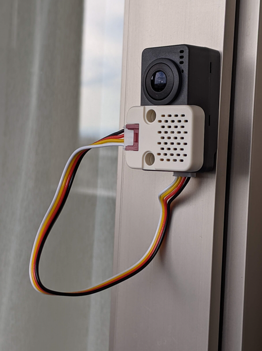
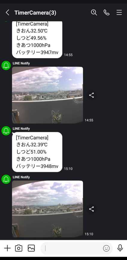
夏休みなので(?)、Timer Camera Fで定点カメラを作ってみました。そのままだと面白くないので、気温・湿度・気圧を取得してLINEに通知するようにしてみました。

Lineに定期的に通知します。

準備
ハードウェア
Timer Camera F https://docs.m5stack.com/en/unit/timercam_f
ENV II https://docs.m5stack.com/en/unit/envII
開発環境
Visual Studio Code https://code.visualstudio.com/
PlatformIO https://platformio.org/
ライブラリー
m5stack/Timer-CAM https://github.com/m5stack/TimerCam-arduino
mobizt/ESP Line Notify https://github.com/mobizt/ESP-Line-Notify
adafruit/Adafruit BMP280 Library https://github.com/adafruit/Adafruit_BMP280_Library
adafruit/Adafruit SHT31 Library https://github.com/adafruit/Adafruit_SHT31
platformio.iniはこのようになります。 upload_speedとmonitor_speedも指定が必要です。
[env:m5stack-timer-cam]
platform = espressif32
board = m5stack-timer-cam
framework = arduino
lib_deps =
    m5stack/Timer-CAM@^0.0.1
    mobizt/ESP Line Notify@^1.0.8
    adafruit/Adafruit BMP280 Library@^2.4.0
    adafruit/Adafruit SHT31 Library@^2.0.0
    adafruit/Adafruit BusIO@^1.8.3
    adafruit/Adafruit Unified Sensor@^1.1.4
    Wire@^1.0.1
upload_speed = 1500000
monitor_speed = 115200
プログラム
写真を取る
初期化
  camera_config_t config;
  config.ledc_channel = LEDC_CHANNEL_0;
  config.ledc_timer = LEDC_TIMER_0;
  config.pin_d0 = Y2_GPIO_NUM;
  config.pin_d1 = Y3_GPIO_NUM;
  config.pin_d2 = Y4_GPIO_NUM;
  config.pin_d3 = Y5_GPIO_NUM;
  config.pin_d4 = Y6_GPIO_NUM;
  config.pin_d5 = Y7_GPIO_NUM;
  config.pin_d6 = Y8_GPIO_NUM;
  config.pin_d7 = Y9_GPIO_NUM;
  config.pin_xclk = XCLK_GPIO_NUM;
  config.pin_pclk = PCLK_GPIO_NUM;
  config.pin_vsync = VSYNC_GPIO_NUM;
  config.pin_href = HREF_GPIO_NUM;
  config.pin_sscb_sda = SIOD_GPIO_NUM;
  config.pin_sscb_scl = SIOC_GPIO_NUM;
  config.pin_pwdn = PWDN_GPIO_NUM;
  config.pin_reset = RESET_GPIO_NUM;
  config.xclk_freq_hz = 20000000;
  config.pixel_format = PIXFORMAT_JPEG;
  config.frame_size = FRAMESIZE_UXGA;
  config.jpeg_quality = 10;
  config.fb_count = 2;

  // camera init
  esp_err_t err = esp_camera_init(&config);
  if (err != ESP_OK)
  {
    Serial.printf("Camera init failed with error 0x%x", err);
    return;
  }

  sensor_t *s = esp_camera_sensor_get();
  //initial sensors are flipped vertically and colors are a bit saturated
  s->set_vflip(s, 1);       //flip it back
  s->set_brightness(s, 1);  //up the blightness just a bit
  s->set_saturation(s, -2); //lower the saturation

  //drop down frame size for higher initial frame rate
  s->set_framesize(s, FRAMESIZE_SXGA);
写真を取る
  camera_fb_t *fb = NULL;
  fb = esp_camera_fb_get();

  if (!fb)
  {
    Serial.println("Camera capture failed");
    return;
  }

  Serial.println("capture complete");
後処理
esp_camera_fb_return(fb);
スリープさせ、一定時間後に復帰させる
以下の処理を行うことで、一定時間スリープして、その後復帰するようになります。 他のM5シリーズとは違うバッテリー制御の仕組みが入っているようです。
- RTCにXX秒後に復帰するよう指定する
- バッテリー出力を止める
RTCにXX秒後に復帰するよう指定する
初期化
bmm8563_init();
sleep_time秒後に復帰
bmm8563_setTimerIRQ(sleep_time);
バッテリー出力を止める
初期化
bat_init();
バッテリー出力を止める
bat_disable_output();
(おまけ)バッテリー残量の取得(単位はmv)
bat_get_voltage()
気温、湿度、気圧を取得する
気温と湿度はSHT30から、気圧はBMP280から取得します。
#define ENV_I2C_SDA 4
#define ENV_I2C_SCL 13

#define BM8563_I2C_SDA 12
#define BM8563_I2C_SCL 14

float tmp = 0.0;
float hum = 0.0;
float pressure = 0.0;

Adafruit_BMP280 bme = Adafruit_BMP280(&Wire);
Adafruit_SHT31 sht3x = Adafruit_SHT31(&Wire);

Wire.begin(ENV_I2C_SDA, ENV_I2C_SCL);
while (!bme.begin(0x76))
{
  Serial.println("Could not find a valid BMP280 sensor, check wiring!");
}
while (!sht3x.begin(0x44))
{
  Serial.println("Could not find a valid SHT3X sensor, check wiring!");
}

pressure = bme.readPressure();
tmp = sht3x.readTemperature();
hum = sht3x.readHumidity();
LINEに送る
LINE Notifyというサービスを利用して通知します。トークンが必要なので事前に取得してください。 https://notify-bot.line.me/doc/ja/
LineNotiFyClient line;
const char *line_token = "xxxxxxxxxxxxxxxxxxxxxxxxxxxx";

line.reconnect_wifi = true;
line.token = line_token;
line.message = "メッセージ";

line.image.data.blob = fb->buf;    // 撮影した画像
line.image.data.size = fb->len;    // 撮影した画像のバイト長
line.image.data.file_name = "camera.jpg";

LineNotifySendingResult result = LineNotify.send(line);
困った点
RTCとはTimer Camera F内部でI2C通信をしているようで、ENV IIのI2C通信と競合(?)して、同時に使うことができませんでした。 色々試行錯誤しましたがいい解決方法は見つからず、
- まずはENV IIから気象データを取得する
- 次にI2C通信を初期化して、RTCの処理を行う
として逃げることにしました。
ソースコード
こちらにも公開しております。 https://github.com/moritalous/TimerCamera-ENVII-LINE
#include <Arduino.h>
#include <WiFi.h>

#include "battery.h"
#include "led.h"
#include "bmm8563.h"

#include "esp_camera.h"
#include "camera_pins.h"

#include <ESP_Line_Notify.h>

#include <Wire.h>
#include "Adafruit_Sensor.h"
#include "Adafruit_BMP280.h"
#include "Adafruit_SHT31.h"

const char *ssid = "xxxxxxxxxx";
const char *password = "xxxxxxxxxx";

const char *line_token = "xxxxxxxxxxxxxxxxxxxx";

int sleep_time = 15 * 60;

#define ENV_I2C_SDA 4
#define ENV_I2C_SCL 13

#define BM8563_I2C_SDA 12
#define BM8563_I2C_SCL 14

float tmp = 0.0;
float hum = 0.0;
float pressure = 0.0;

Adafruit_BMP280 bme = Adafruit_BMP280(&Wire);
Adafruit_SHT31 sht3x = Adafruit_SHT31(&Wire);

LineNotiFyClient line;

String message = "";

void enterSleep()
{
  Serial.println("Enter Sleep! Wake Up after " + String(sleep_time) + " Sec.");
  delay(500);
  Wire.begin(BM8563_I2C_SDA, BM8563_I2C_SCL);
  delay(500);

  bmm8563_init();
  bmm8563_setTimerIRQ(sleep_time);

  bat_disable_output();

  esp_deep_sleep(sleep_time * 1000 * 1000);
  esp_deep_sleep_start();
}

void setup()
{
  Serial.begin(115200);
  Serial.setDebugOutput(true);
  Serial.println();

  bat_init();

  led_init(CAMERA_LED_GPIO);

  Wire.begin(ENV_I2C_SDA, ENV_I2C_SCL);
  while (!bme.begin(0x76))
  {
    Serial.println("Could not find a valid BMP280 sensor, check wiring!");
  }
  while (!sht3x.begin(0x44))
  {
    Serial.println("Could not find a valid SHT3X sensor, check wiring!");
  }

  pressure = bme.readPressure();
  tmp = sht3x.readTemperature();
  hum = sht3x.readHumidity();

  message = "\r\nきおん" + String(tmp) + "℃\r\n" +
            "しつど" + String(hum) + "%\r\n" +
            "きあつ" + String((int)pressure / 100) + "hPa\r\n" +
            "バッテリー" + String(bat_get_voltage()) + "mv";

  camera_config_t config;
  config.ledc_channel = LEDC_CHANNEL_0;
  config.ledc_timer = LEDC_TIMER_0;
  config.pin_d0 = Y2_GPIO_NUM;
  config.pin_d1 = Y3_GPIO_NUM;
  config.pin_d2 = Y4_GPIO_NUM;
  config.pin_d3 = Y5_GPIO_NUM;
  config.pin_d4 = Y6_GPIO_NUM;
  config.pin_d5 = Y7_GPIO_NUM;
  config.pin_d6 = Y8_GPIO_NUM;
  config.pin_d7 = Y9_GPIO_NUM;
  config.pin_xclk = XCLK_GPIO_NUM;
  config.pin_pclk = PCLK_GPIO_NUM;
  config.pin_vsync = VSYNC_GPIO_NUM;
  config.pin_href = HREF_GPIO_NUM;
  config.pin_sscb_sda = SIOD_GPIO_NUM;
  config.pin_sscb_scl = SIOC_GPIO_NUM;
  config.pin_pwdn = PWDN_GPIO_NUM;
  config.pin_reset = RESET_GPIO_NUM;
  config.xclk_freq_hz = 20000000;
  config.pixel_format = PIXFORMAT_JPEG;
  config.frame_size = FRAMESIZE_UXGA;
  config.jpeg_quality = 10;
  config.fb_count = 2;

  // camera init
  esp_err_t err = esp_camera_init(&config);
  if (err != ESP_OK)
  {
    Serial.printf("Camera init failed with error 0x%x", err);
    return;
  }

  sensor_t *s = esp_camera_sensor_get();
  //initial sensors are flipped vertically and colors are a bit saturated
  s->set_vflip(s, 1);       //flip it back
  s->set_brightness(s, 1);  //up the blightness just a bit
  s->set_saturation(s, -2); //lower the saturation

  //drop down frame size for higher initial frame rate
  s->set_framesize(s, FRAMESIZE_SXGA);

  Serial.printf("Connect to %s, %s\r\n", ssid, password);

  WiFi.begin(ssid, password);

  int count = 0;
  while (WiFi.status() != WL_CONNECTED)
  {
    delay(500);
    Serial.print(".");
    count++;
    if (count > 20)
    {
      enterSleep();
    }
  }
  Serial.println("");
  Serial.println("WiFi connected");
}

/* Function to print the sending result via Serial */
void printRessult(LineNotifySendingResult result)
{
  if (result.status == LineNotify_Sending_Success)
  {
    Serial.printf("Status: %s\n", "success");
    Serial.printf("Text limit: %d\n", result.quota.text.limit);
    Serial.printf("Text remaining: %d\n", result.quota.text.remaining);
    Serial.printf("Image limit: %d\n", result.quota.image.limit);
    Serial.printf("Image remaining: %d\n", result.quota.image.remaining);
    Serial.printf("Reset: %d\n", result.quota.reset);
  }
  else if (result.status == LineNotify_Sending_Error)
  {
    Serial.printf("Status: %s\n", "error");
    Serial.printf("error code: %d\n", result.error.code);
    Serial.printf("error msg: %s\n", result.error.message.c_str());
  }
}

void loop()
{
  // put your main code here, to run repeatedly:

  camera_fb_t *fb = NULL;
  fb = esp_camera_fb_get();

  if (!fb)
  {
    Serial.println("Camera capture failed");
    return;
  }

  Serial.println("capture complete");

  line.reconnect_wifi = true;
  line.token = line_token;
  line.message = message.c_str();

  line.image.data.blob = fb->buf;
  line.image.data.size = fb->len;
  line.image.data.file_name = "camera.jpg";

  Serial.println(message);

  LineNotifySendingResult result = LineNotify.send(line);
  printRessult(result);

  esp_camera_fb_return(fb);

  enterSleep();
}
ESP32をAWS IoTにつなぐ3つの方法
過去にQiitaに投稿した内容のアーカイブです。
ESP32をAWS IoTにつなぐ方法です。 自分用のメモです。
Arduino+外部ライブラリー(MQTT+ArduinoJson)
簡単度:★★★★★
一般的なArduinoのライブラリー(MQTTとArduinoJson)を使って実現します。
参考 https://github.com/aws-samples/aws-iot-esp32-arduino-examples https://aws.amazon.com/jp/blogs/compute/building-an-aws-iot-core-device-using-aws-serverless-and-an-esp32/
Arduino+AWS製ライブラリー
期待度:★★★★★
aws-samplesのリポジトリ内で開発されています。Amazon iot C-SDKに存在しないGreengrass部分を開発しているようです。 名前がGreengrassとなっていますが、AWS IoTと直接やり取りすることもできます。
参考 https://github.com/aws-samples/arduino-aws-greengrass-iot
FreeRTOS
本気度:★★★★★
お手軽ではありませんが、AWS謹製でございます。おそらく新機能も一番早いでしょう
[ネタ]iPhone Xに物理ホームボタンを追加する[ネタ]
過去にQiitaに投稿した内容のアーカイブです。
最近のiPhoneって、ホームボタンないんですってね。 ホームボタンあったら、嬉しいですよね? Android使いなのでよくしらないですが。
ESP32を使って物理ボタンを追加しましょう。
仕組み
ArduionoのライブラリーでBluetoothキーボードにできるものがあったので、これを使います。
ESP32-BLE-Keyboard https://github.com/T-vK/ESP32-BLE-Keyboard
準備するもの
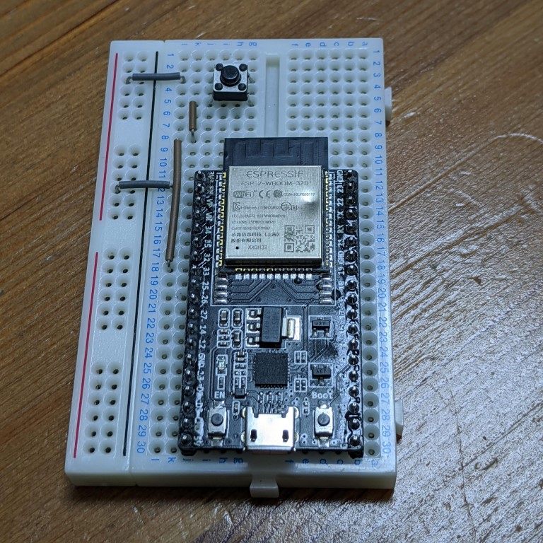
ESP32-DevKitC V4 ブレッドボード タクトスイッチ
こんな感じです。

ソース
タクトスイッチが押されたらcommand + Hを送ります。それだけです。
#include <Arduino.h>
#include <BleKeyboard.h>

BleKeyboard bleKeyboard;

const int switchPin = 32;

int currentState = 0;
int beforeState = 0;

void setup()
{
  Serial.begin(9600);
  pinMode(switchPin, INPUT);

  bleKeyboard.begin();
}

boolean isChange(int current, int before)
{
  return (current != before) && (current == 1);
}

void loop()
{
  currentState = digitalRead(switchPin);

  if (isChange(currentState, beforeState))
  {
    Serial.println("Change!!!");

    if(bleKeyboard.isConnected()) {
      bleKeyboard.press(KEY_LEFT_GUI);  // Windows key
      bleKeyboard.press(0x68);  // H key
      delay(100);
      bleKeyboard.releaseAll();
    }
  }

  beforeState = currentState;

  delay(100);
}
使ってみた
手元にあるiPadで試してみました。
Bluetoothの設定にてESP32 BLE Keyboardとペアリングをすれば準備完了。
タクトスイッを押せばホーム画面に戻ります!期待通り!
ただし!物理キーボードが接続されていると判定されるので、テキスト入力が必要なところでソフトウェアキーボードが出ません!!!
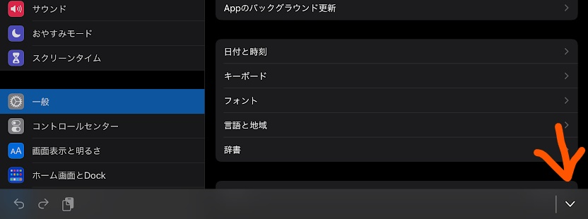
どうしても使いたい場合は、下向き三角(下図)を長押しするとソフトウェアキーボードが出てくれます。一度ソフトウェアキーボードが出る状態になると、次からもソフトウェアキーボードが出ます!

やった! これで、物理ホームボタンの完成です!